
 Tweet
Tweet
I have an older danby with a thermostat. The compressor seems to work fine, as I've noticed it cycles on/off. However, even when I have the thermostat at the coldest setting, the liquid temp won't get lower then 44 degrees. So, I'm thinking about adding an external controller, but want to make sure exactly which wires to splice together. I assume I just cut the red and black where they enter the thermostat and splice together. Below are pics of the wiring diagram and the thermostat. Thanks for the help!
-
Last edited by hops; 01-05-2011, 07:38 PM. -
That will do it.Originally posted by hops View PostMalt is the soul of beer... and yeast gives it life..
but the kiss of the hop is the vitality of that life!
My three favorite beers: The one I just had, the one I'm drinking now and the next one I'll have.
http://kegerator-social-network.micr...bygrouptherapyComment
-
Thanks for the quick response! I'll give it a shot.Comment
-
Hello all.
I just wanted to report that the 33k resistor mod I performed 2 years ago is still working perfectly. To restate, I bought a spare temp sensor from Danby for $10.00 shipped. I used that one for the mod. The original one I put in a box to save. I added extra wire so the sensor is hanging down a little from the top left front. The soldered resistor is tucked neatly in the compartment on the side. I tucked the extra length of wire carefully behind the back plate.
I velcro mounted a remote thermometer inside the Danby.
I set the Danby at 41. The inside temp is 34. Beer is 34-36 in the glass.
TWO YEARS!Comment
-
I'd also like to thank all of the diligent work that has been displayed here and in other Danby threads on all the mods. I just acquired a Danby from my neighbor and after reading through this and the other threads, I believe I have all the mods well in hand. The mod parts arrived yesterday, so I'll be spending my 3-day weekend putting everything together.
In my case, I'll be going with the 33k resistor fix, along with the two computer fans to chill the tower and move air around the kegerator itself. My thought is that a $0.99 fix is better than a $75 fix. That, and I'm already stretching my electronics knowledge to the limit coming up with the two fan mod.
When I'm done, and after I test everything with a 5-gal carboy of water, I hope to report back in with my results. I just can't wait to finally have kegged commercial beer and homebrew available at the throw of a tap. A follow-up report with pictures is forth-coming! I owe all of those who have worked so hard at updating us that.
Slainte!Comment
-
i installed the Johnson control and a bigger fan inside with a smaller one pointed up towards the tower it seems to be working fine.. but i have a question.. should the fan inside run at all times or should it turn on when the compressor turns on?? also the display shuts off because i plugged it into the new thermostat.. anyway around that to keep it on at all times.. thanks.Last edited by padilla399; 01-18-2011, 06:55 PM.Comment
-
I wanted to update you on my process thus far with my Danby mods. I was really hoping that the resistor fix would take care of the problems I'm having with temperature control. Even after hard-wiring a 100k resistor, I'm still seeing that my 5-gallon carboy of water is going between 37-40 degrees. Not cold enough for me. So I believe that I'll have to resort to Plan B - getting the Johnson Control A419 and hard-wiring it to the Danby to take over the temp. I do have some electrical background, but I still am having issues visualizing the mods that have been described here. What I've done is taken several pictures of my kegerator, and I'm hoping you can advise me from here on what to do.
I have found an opening on the back-bottom-right of the kegerator (as you face it). I took the panel off, and the pics you see are from that perspective. I did not see a control board there, but I'm hoping I can hook the A419 in through this panel as it's where the AC power comes in. If I am wrong in this assumption, please let me know and I can do some more searching. Here are the pics that I've taken to help you:
DSCN0261a - The schematic for my kegerator
DSCN0264a - A shot centered on the interior from the panel I removed
DSCN0268a - Another shot looking down into the panel (note AC come in from bottom right)
DSCN0269a - Final shot with wires pulled out more
Given this, can I wire the A419 into the kegerator through here and take over control? If so, how? Also, if so, can I still have the display show the temp inside the kegerator? If I need to search further for the control board on the kegerator, where should I start looking?
Again, I appreciate any help. Thanks in advance!Last edited by djdeity; 01-21-2011, 06:14 PM.Comment
-
This is the same model I have. The control board is underneath the top behind the tower. I posted pics on how I hooked up my JC under the thread -What Johnson Control should I get- or just follow the link below. Hope this helps. It is wired so that the digital led readout stays on in the front also.
Last edited by joewilk; 01-23-2011, 05:44 PM.Comment
-
Again, please forgive me as I really can't visualize all this as it works together.Originally posted by joewilk View Post
1) Where is the JC control unit? Is it getting power from the bottom-right of the kegerator as pismo10 described? Or are the wires to the JC coming directly from the control panel?
2) I'm confused by the pics you've posted on the thread you noted. The "before" and "after pics show a new black wire grouping coming in from the top. Is that a wire that you added - going into the JC? If so, what kind of wire is it so that I can get the same?
2a) Again, assuming the top black grouping is one coming in via the JC, I am guessing that the two black wires coming from the control panel are cut, and joined by a wire nut with the black wire from the black grouping at the top.
2b) Is this the same for the white wires as well - the white wire from the grouping nutted together with the two white wires coming from the control panel?
2c) Then there's the 2 red wires from the control panel. It looks as though the red wire coming directly off the control panel to the left is cut and put into a wire nut - making it basically dead. And then the red wire coming from the right-side of the control panel, tied with a white wire, is combined with the green wire off the black grouping. But wouldn't that mean that the red wire, going down at the top right is completely bare?
Again, I apologize for my confusion, but I just can't fully visualize how this comes together. With limited electrical knowledge, I want to make sure my next moves are correct.Comment
-
I have the JC mounted on the back of the unit. I used velcro to secure it. The jC unit is getting power directly from the control board. So when the Danby is on..the JC is on.
The Black wire that you see in the pic is the power cord coming from the JC. I ordered the JC unit that didnt have a lead so I had to add it. I just used a piece of old extention cord I had around the garage. If yours does not have a lead you will need to add one. I posted a pic on how to wire that into the JC unit also.
In the pic below I show you what wires need to be cut. The brown wire is for the condensor fan and I did not cut that one because I wired it directly to the compressor. You would wire that one in with the red wires.
2a and 2b are correct.You wire the black wires you cut back together and wire the JC black wire in with it. And wire your white wires back together along with your JC white wire in it.
With the red wires you cut you want to wire nut the red wire still connected to the plug end. It is not dead but it will take control away from the Danby's temp unit and give it to the JC while still being able to read the front led. Wire the other half of the red wire to the red wire coming from the JC lead.
To sum it up, Wire the Black wires together, Wire the white wires together and wire the 2 red wires together. I put together a photo to help a little more. The green represents the black wire in the top pic. Hope this helps.
[IMG]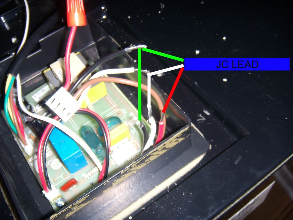 [/IMG]
[IMG]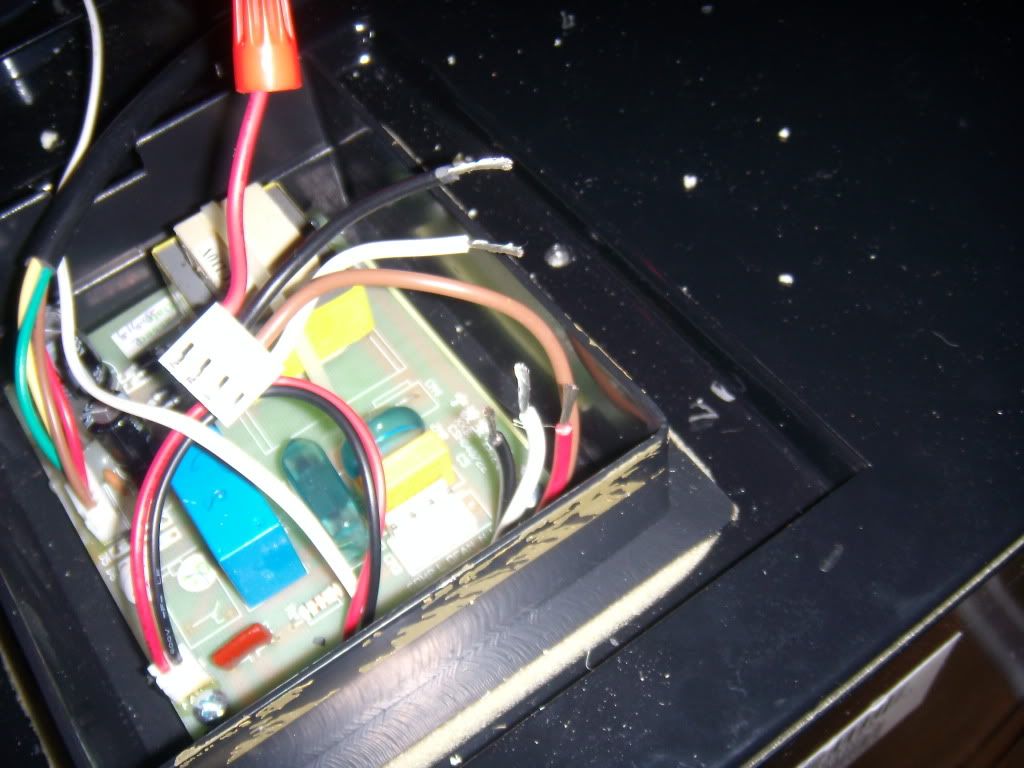 [/IMG]
Comment
-
I appreciate your pictures, joewilk. They look clearer to me than a few of the others I've seen. I do have further questions for you for my understanding. I have been working with pismo10 from his post #49 in this thread to try to get the JC controller connected through the bottom right panel. It looks like an easier proposition, as you don't have to take the entire top off the kegerator to achieve the same effect. However, I'm still confused on some of his directions and I'm looking for a "Plan B."
Below is a picture of my control board. Given my picture, yours, and your instructions, here's what I've been able to understand:
1) Run an old extension plug wire up to the control panel. This will connect the JC control to the wires noted in the following steps. In running this wire, is there a conduit below the control panel that will make this easier?
2) Remove the plug noted below from the control panel.
3) Cut the black wire in half, strip the two ends, and connect by wire nut to the black wire running to the JC control.
4) Cut the white wire in half, strip the two ends, and connect by wire nut to the white wire running to the JC control.
5) Cut the red wire in half. Terminate the red wire still connected to the plug with a wire nut. Connect the remaining red wire to the red wire going to the JC control.
6) Reconnect the plug to the control board.
7) With these changes made, I go back to the JC control and wire in the black, white, and red wires into the JC using the diagram shown previously by frozone in his post #19.
Are these steps correct? And if so, does the front display on the kegerator still function to show that it is operating?
Thanks for the help!

Comment
-
Just a follow-up to my above post. I've connected everything according to the steps I listed above. Frozone noted that you really have to be careful where you cut the wires near the control board, because it's tight. He wasn't kidding. Thankfully, when I plugged it in, it's up and running. Will find out in the next day or so if I got it right.
Next up is building the tower cooler... then finally, beer! Thanks for everyone's input!Comment
-
Yes, It sounds like you did it right. And sorry for not warning you about the tight wires. It is VERY tight. Glad it worked for you. I also posted a youtube video on how to build a tower cooler. Look for the thread ( Tower cooler instructions YEAH!! ) It has a link on it that leads you to a step by step video on how to do so.Comment
-
Actually, I've seen your video, and I'm using it for the template on my cooler. Thanks for that!
I know that I'm probably watching this thing way too closely right now, but I wonder if I've run into a problem. I've noticed that the compressor and fan have been turning off and on somewhat randomly right now before the inside reaches the target temp. I'm wondering if this is the JC's anti-short delay or something like that at play. I know that I really won't know if the changes have worked until more than 24 hours of cooling have passed, but I'm just wary right now.Comment
-
Thanks psychodad for all you do. I've got a Danby DKC644BLS. I bought a manual JC A19 which plugs into the wall. I would like to have the Danby display working.
I removed the top of the kegerator to access control board. I unplugged the white tab with red, black and white wires from the control board. I cut the red and black wires and spliced them together. Capped the red wire coming from the board. Is this right?
How do I feed the JC A19 probe thru the CO2 hole?
Thanks for your help.Last edited by mhop10; 03-01-2011, 10:54 PM.Comment

Comment