
overview
mav closed system
MAV (MACRO VALVE) CLOSED LOOP SYSTEM
For Returnable/Refillable & On-Site Refilling Multi-Use Applications.
For Filling/Refilling & Dispensing.
The MAV Closed Loop System is designed for use with a Pump or Pressure to transfer product and can simply be integrated with drums, IBC (totes) and custom / specialty packages.
Reuse, Refill & Repeat
MAV CLOSED LOOP SYSTEM -FEATURES & BENEFITS
Fulfills the requirements of Directive 97/23/EC concerning pressure equipment.
Maximum working pressure 6 bar - Dispense Coupler can be equipped with a PRV (pressure relief valve) of 1 or 2 bar.
Max/min working temperature +45ºC / -10ºC (113ºF / 14ºF).
The details that make the difference

1. Fill Coupler
Closed, Sealed & Secure
Spring actuated and self-closing upon disconnect keeps product contained within the dispense hose, eliminating any chance of spills. Dry Disconnect - Less than 2 milliliters.
Reusable - Durable Stainless Steel Construction
Provides many years of service life.
Vapor Recovery Outlet
Creates a Closed Loop Fill environment.(When used with pump)
Proprietary Keyed System
Controls who can access container for dispensing.(Requires matching keyed MAV Container Valve)
2. Dispense Coupler
Closed, Sealed & Secure
Spring actuated and self-closing upon disconnect keepsproduct contained within the dispense hose, eliminating any chance of spills. Dry Disconnect - Less than 2 milliliters.
Reusable - Durable Stainless Steel Construction
Provides many years of service life.
Vapor Recovery Outlet
Allows for product extraction only, protecting from product adulterations and cross contamination.
Proprietary Keyed System
Protects package from over-pressurizing and used to release any unwanted head pressure.
3. Tamper Evident Pin (Red)
Secures & Protects
Container Valve Through TransportationUsed as best practice for security and protection to ensure packaging integrity.
4. Dust cover
Protects Container Valve Against Debris
Used as best practice for maintaining ultimate product purity and to reduce worker/environmental exposure.
5. Container Valve
Closed, Sealed & Secure
Self-closing upon disconnect, prevents unauthorizedaccess to the product in the container.Dry Break of less than 10 milliliters.
Sustainable Stainless Steel Construction
Protects your investment, providing many years of service life.
Proprietary Keyed System
Controls who can access container for dispensing.
6. Retaining Ring
Secures container valve to container
Requires proprietary Micro Matic Valve Releasing Tool #740-078 to remove MAV Container Valve from container Neck.
7. Tamper Evident Ring
Protects container valve from unauthorized removal
Used as a best practice for security and protection to ensure package integrity.
8. Container Neck
Integrated Adapter
Required to be welded to container for proper installation of MAV Container Valve.
9. Down Tube
Maximizes Product Yield
Length designed to reach and locate in container sumpfor optimum product extraction and to minimize waste(100 milliliters or less).
CONTAINER VALVE - INSTALLATION INSTRUCTIONS
How To Create the MAV Closed System Container Package. Install & Secure MAV Container Valve into Container
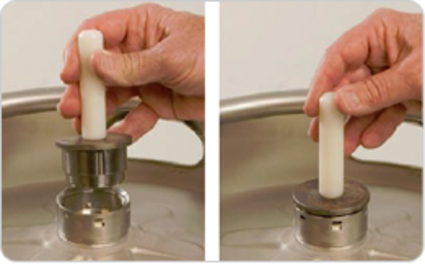
Check Continer Neck
Use "Go Gauge" tool #001-619 and insert into continer neck. Go Gauge should fit completely down inside container neck as shown. If Go Gauge does not fit in neck, do not use continer.
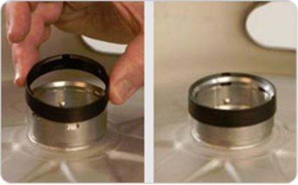
Install Tamper Evident Ring
Place Tamper Evident Ring over Container Neck. Tamper Evident Ring is properly installed when it sits approximately 1/8" from being flush with Container Neck top opening.
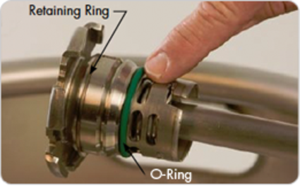
Inspect Container Valve
Inspect Container Valve O-Ring and Retaining Ring for damage. O-Ring should not appear cracked or cut and Retaining Ring must be present and secured to container valve.
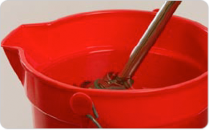
Prime Container Valve
Submerge Container Valve Body in a bucket of clean water prior to mounting.
NOTE: If water cannot be used during installation contact your Micro Matic representative.
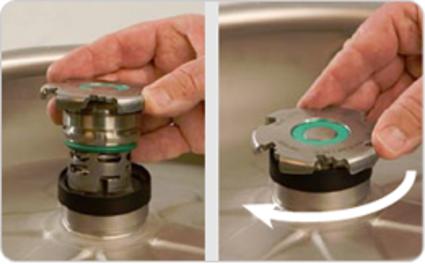
Mount Container Valve
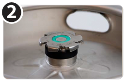
Place Container Valve into Container Neck. Turn Container Valve clockwise until it drops. Now turn the Contianer Valve 1/2 turn clockwise until it drops again and locks into place.
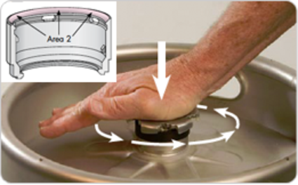
Seat Container Valve
IMPORTANT: It is necessary to seat the Container Valve properly in the neck prior to step 7. While pressing down, rock the palm of your hand in a circular pattern. This will center the retaining ring evenly across area 2 on the neck.
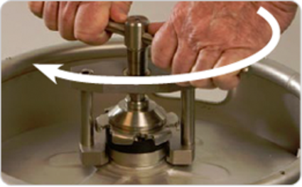
Lock Container Valve to Container
Place Spindle Tool #740-076 over container valve as shown and secure in place by turning the spindle handle clockwise until no more clicks are heard Loosen the spindle handle until free, rotate the spindle tool 1/2 turn and retighten to insure no clicks are heard. Remove Spindle Tool.
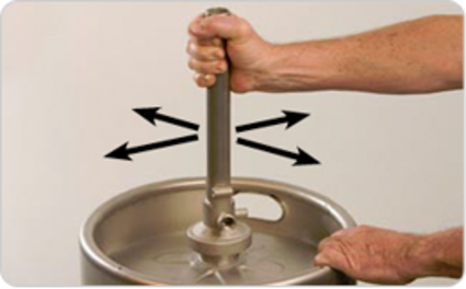
Verify For Proper Installation
Verify that the contianer valve has been installed correctly by using the Verification Tool #741-043. Place the service tool on the container valve flange and rotate 1/6 of a turn clockwise. Using controlled force, move (rock) the Verification Tool side to side & back and forth. An incorrect seated valve will come loose during this operation. If neccessary, repeat steps 6-9.
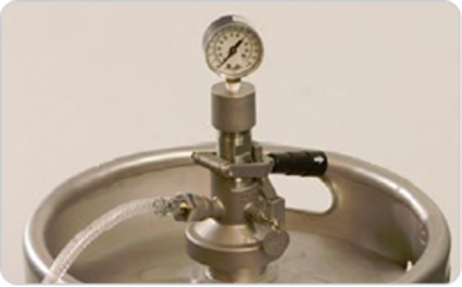
Conduct Pressure Test
Optional: Pressurized Leak Testing by using the MAV Pressure Test Head #748-039 (EPDM), #748-042 (Viton). For additional information call (866) 755-4477.
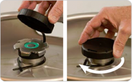
Install Dust Cap
Secure around container neck, insert cap over container valve and turn clockwise to lock into place.
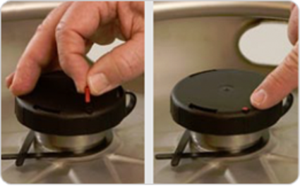
Secure Tamper Evidence
Install Red Tamper Evident Pin #102-423 by inserting into hole located on the top of the dust cap. Push red pin down until it is flush with the surface of the dust cap.
DISPENSE & FILL COUPLER - CONNECT & DISCONNECT INSTRUCTIONS
It’s Simple As Turn, Click & Go!
CONNECT
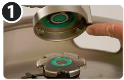
Remove Dust Cap
Remove Dust Cap by turning counter clockwise. NOTE: During this process the Tamper Evident Red Pin will break and be distroyed. To apply Tamper evidence a new Tamper Evident Pin will be required to be installed.
Engage Coupler
Align MAV Coupler pins with slots in Container Valve. Insert MAV Coupler into Container Valve.
NOTE: Ensure that handle is in the off/closed (up) position.
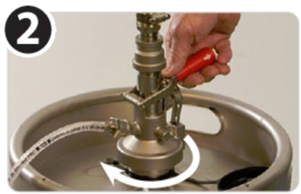
Turn, Click & Lock
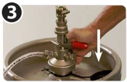
Turn Dispense Coupler clockwise until it stop (approx. 1/6 of a turn). Push down handle down. Handle will click and remain in the on/open (down) position.
CAUTION: The handle cannot be pushed down if incorrectly connected. If neccessary, repeat steps 2-4.
DISCONNECT
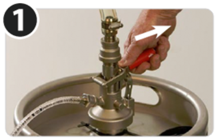
Unlock Coupler
Pull handle outward and allow handle to release into the off/closed (up) position. The system is now closed.
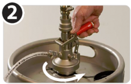
Turn Handle Counter-Clockwise
By turning handle counter-clockwise, Dispense Coupler will unlock from container valve.
Pull Up & Remove
When Dispense Coupler cannot turn counter-clockwise anymore, remove by lifting up.